Such a tiny thing. It weighs only 9 grams, but the moment of strength has quite large, 1,6 kg/cm.
It is powered by 4.8-6V voltage, the maximum current is 800 mA.
Of course, most of us are interested in how to control this servomechanism. Well, it is controlled by pulses with a modulated width.
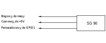
We have three outputs, power supply (red), mass (brown), and control (orange). If on the orange contact is put a signal with a period of 20 ms, and 1 for 1.5 ms, the servo shaft is in the middle position. If 1 is 0.6 ms, it turns to the rightmost position, 2.5 ms - to the leftmost position.
Although the producer states, that the logical 1 is 5V, the signal from the GPIO pin, 3.3V, also works.
The signal is needed only for the time necessary to perform the given rotation, the built-in four-speed gear causes that the servo shaft remains in its position even after turning off the power, it will not turn by itself.
We connect the power supply, generate the PWM signal, connect it to the servo control and it's done. I have already described how to deal with PWM in Raspberry Pi in the GPIO PWM section, so let's focus on SG90 control process.
Let's connect our servo. The orange cable to the GPIO pin 1 (physically pin 12), brown to ground, red to power. We can connect the red cable to 5V on the GPIO connector, but due to the large current that the servo might take, even 800 mA, it is better to connect it directly to the output of the power supply:

We can connect the control line to another available GPIO pin, but if we use a hardware PWM generator, it must be one of the pins that support it.
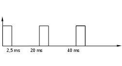
Now we have to generate the control signal. We need a rectangular wave, with a period of 20ms and a pulse width between 0.5 ms and 25 ms. The waveform 2.5 ms will turn the servo shaft to the leftmost position:

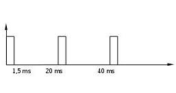
1.5 ms will put the shaft in the middle position:

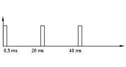
0.5 ms will turn it to the rightmost position:

Of course, the pulse with a different width, between 0.5 and 2.5 ms, will cause a turn on the corresponding angle between 0 and 180°.
In the simplest scenario, we can generate the rectangular waveform by software, as it is done in the serv.c program (compilation script cs).
It generates a rectangular signal by software, measuring the duration of a logical 1 and the duration of the break time:
for (time = 500; time <2500; time = time + STEP)
    {
     printf ("% d ms \ n", time); fflush (0);
     for (i = 0; i <10; i ++)
      {
       digitalWrite (1, HIGH);
       Delay (time);
       digitalWrite (1, LOW);
       Delay (PERIOD-time);
      }
     Delay (PAUSE);
    }
Creates a rectangular wave signal with a duration of a logical 1 from 0.5 ms to 2.5 ms, increasing this time every 0.3 s by 0.02 ms.
If you run this program, the servo shaft will turn in tiny increments, similar to the second's hand on a watch does.
The advantage of such a software solution is its simplicity, secondly, just one Raspberry Pi can control by up to 28 servos (if I counted correctly, this is the number of pins on the GPIO connector that can be set as output).
Unfortunately, this method also has a disadvantage, which can be significant if we want to precisely and reliably control our servo.
The duration of a logical 1 and the period of the signal are calculated with a nanosecond resolution, but our program works on the multitasking system.
There is no guarantee that our process is active at the time when the precisely counted period of time has elapsed. Most likely, it will be politely waiting in the queue for the kernel to draw him from among several hundred others, also waiting.
As a result, instead of the expected pulse of e.g. 1.25 ms, will appear 1.31. The servo will of course begin to obediently move the shaft to the position corresponding to the 1.31 ms pulse.
If you run the serv.c program, you will surely notice that the servo shaft sometimes acts as if it has a hiccup.
The solution to those inaccuracies is a hardware PWM generator, which, of course, our Raspberry Pi computer has.
We will use the servp.c test program (compilation script csp).
This program controls the servo shown in the video available at the top of this section.
If we skip the nuances of pwm itself, it's very simple.
We program the PWM channel, 0.1 ms clock, 20 ms period:
   pinMode (1, PWM_OUTPUT);
   pwmSetMode (PWM_MODE_MS);
   pwmSetClock (1920);
   pwmSetRange (200);
We move the shaft twice from one extreme position to another, stopping in the middle:
   for (i = 0; i <2; i ++)
     {
      pwmWrite (1.6);
      sleep (1);
      pwmWrite (1.15);
      sleep (1);
      pwmWrite (1.25);
      sleep (1);
      pwmWrite (1.15);
      sleep (1);
     }
Now we turn the servo shaft from one extreme position to the other, increasing the duration of a logical 1 in increments of 0.1 ms (9°). After each reprogramming of the generator (pwmWrite(1,i);), in a simple loop we add a small delay so that the servo has time to turn the shaft:
     for (i = 6; i <26; i ++)
       {
        pwmWrite (1, i);
        for (j = 0; j <30,000,000; j ++);
       }


 Polski