In everyday life, we often encounter signals type open-close.
It can be a simple mechanical switch detecting opening a door, a twilight switch, a keyboard key, a signal from a more complicated device, for example, from an alarm control panel or fire alarm switchboard.
The signal may come from contacts of an ordinary mechanical switch, relay contacts, or it may be an open collector signal.
Handling this type of signal by Raspberry Pi is trivial. We have already used it to operate a keypad or to count pulses. However, this was done while discussing other problems, and it may not have received sufficient attention, so we will discuss this issue separately.
So as to not focus too much on theory, let's describe a simple system for signaling an open gate.
Can it be useful? It can.
A real-world example:
A puppy ran out into the street at night, which ended tragically for him. Probably someone forgot to close the gate in the evening.
So let's equip our gate with a simple mechanical switch that opens the contacts after opening the gate, and our Raspberry Pi, if it is not closed again after a set time, for example, two minutes, will react to this by activating light and sound signals, send a text message or activate a gate closing mechanism if it has one.
The GPIO pins are equipped with resistors (let's agree that 50kΩ, although different sources give the range 40 - 100kΩ - this is not particularly important), which can be used to connect the pins to ground or power supply (3.3V). These resistors are part of the BCM2xxx chip (x - differs with Raspberry Pi versions), they can be turned on and off by software. Unfortunately, it is not possible to programmatically read which of them are currently active.
Certain exceptions are pins 8 and 9 (according to WiringPi, 2 and 3 according to BCM in Raspberry Pi rev.2), which have additional external 1.8 kΩ resistors permanently connected to the supply voltage. They are used to control the I2C bus. We cannot programmatically connect these pins to ground.
So, if we program the GPIO pin to input and turn on the resistor connected to the supply voltage, we will read a logical 1 on it (if we do not force another state using an external signal). Similarly, if we turn on the resistor connected to ground, we will read a logical 0.
It is that simple. We choose any free pin, connect our switch (relay contacts) to this pin and ground, and the hardware is ready.
Now software part.
As in other examples, we will use the wiringPi library. If you do not have it and do not know how to install it, please take a look at this page.
Using this library we can program the pin as input or output:
void pinMode (int pin, int mode) ;
pin is of course the GPIO pin number. As mode we can use INPUT, OUTPUT, or PWM_OUTPUT.
The first two parameters are probably self-explanatory, the third is the pulse width modulation.
The second function that interests us is:
void pullUpDnControl (int pin, int pud) ;
It will connect the resistor to the power supply (PUD_UP), to ground (PUD_DOWN), or disconnect both (PUD_OFF).
And now this function:
int digitalRead (int pin) ;It will return the logical state (0 or 1) of the given pin.
Now the software. As usual, an example program and a simple compilation script.
#include <stdio.h>
#include <stdlib.h>
#include <wiringPi.h>
We define the time during which the gate can be opened without raising the alarm:
#define CZAS 7200 // Czas otwarcia bramy, 2 minutyWe define the pins to which we will connect the gate opening sensor and alarm signaling device:
#define PIN_WYL 25  // Pin do ktorego podlaczamy czujnik bramy
#define PIN_ALARM 24  // Pin do ktorego podlaczamy alarm

void alarm();


int main (void)
{
int i;
int czas_otw;
Initialization of the wiringPi library structures:
  if (wiringPiSetup() == -1)
  {
    printf("wiringPi-Error\n");
    exit(1);
  }
The pin of the opening sensor we program as input and turn on the resistor connecting to 3.3V:
 pinMode(PIN_WYL, INPUT);
 pullUpDnControl(PIN_WYL, PUD_UP);
The pin of the alarm signal we program as output and set it to the state of a logical 0:
 pinMode(PIN_ALARM, OUTPUT);
 digitalWrite(PIN_ALARM,LOW);
Now, in an infinitive loop, we check the status of the gate sensor:
for (;;)
 {
  if(digitalRead(PIN_WYL)==0)   //brama zamknieta, styk czujnika zwarty
   czas_otw=CZAS;
  else
   czas_otw--; // brama otwarta, odliczamy kolejne sekundy otwarcia
  sleep(1); // sekunda opoznienia do kolejnego testu czujnika
  if (czas_otw==0) // licznik sekund otwarcia sie wyzerowal
   {
    alarm(); // brama za dlugo otwarta, zareaguj
    czas_otw=CZAS; // jesli brama mimo alarmu nie zostanie zamknieta,
                   // po czasie CZAS ponownie uruchom alarm
   }
 }
The alarm function. It can do anything, activate an actuator that closes the gate, send a text message, etc. In our example, it will activate three times a sound signal device (optical) connected to the PIN_ALARM pin, for 3 seconds with 1-second intervals.
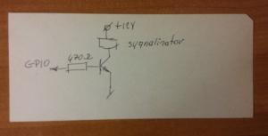
Of course, the signal device cannot be connected directly to the GPIO pin. In the state of a logical 1, there will be about 3.3V voltage. The maximum current that can be obtained from a single pin is about 16 mA, and the sum of all currents flowing from the GPIO pins should be less than 50 mA.
It is not much, in addition, it is better not to get close to these limits, so we will connect our signaling device, for example, through a transistor:
}
void alarm()
{
  digitalWrite(PIN_ALARM,HIGH);
  sleep(3);
  digitalWrite(PIN_ALARM,LOW);
  sleep(1);
  digitalWrite(PIN_ALARM,HIGH);
  sleep(3);
  digitalWrite(PIN_ALARM,LOW);
  sleep(1);
  digitalWrite(PIN_ALARM,HIGH);
  sleep(3);
  digitalWrite(PIN_ALARM,LOW);
  sleep(1);
}
And finally, a question. Do you know on what I scribbled this diagram? It is a punch card. It is almost half a century old. Programs and data were coded on cards like this. Capacity? 80 10-bit characters.


 Polski