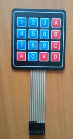
A simple keypad like this is cheap and easily affordable:
It may not be as sturdy as a mechanical one and it will not withstand mass data entry, but it is fine for occasional use.
There are no electronics in it, which is an advantage (it will not overheat or freeze), but also a disadvantage, because to read it we have to use an external program that controls eight pins.
We can add some electronics, then we will reduce the number of supported signals, but is it worth it?
In that case, it is better to buy a more expensive toy but already with a USB interface.
How does it work? It's simple. We have four lines connected to the keypad's rows and four to its columns. For example, by pressing the "4" key, we are closing the line of the second row with the line of the first column.
Just enter a logical one on the subsequent rows' lines and check whether it appears on any of the columns' lines. And since there are no electronics here, this logical one can be of any type of signal, CMOS, TTL, 12V, whatever suits us. Well, maybe with some restrictions, 3 kV would be rather an exaggeration, for obvious reasons.
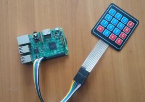
So let's connect it. We choose 8 GPIO pins that are not yet in use and connect them with the keypad pins.
I chose GPIO22 - GPIO29. They are close to each other so the cables are less tangled.
After connecting, it looks like this:
Unfortunately, with this selection of pins, you cannot connect the keypad plug directly to the GPIO header, you need an extension cable.
If we choose the GPIO pins: 6, 10, 11, 31 and 22, 23, 24, 25, the keypad ribbon cable could be connected directly, but we would have to replace its eight-pin connector with two four-pin connectors.
I prepared an example, ready to use, program called keyb.c and a simple script to compile it called ckWell, now how it works.
We define to which GPIO pins the outputs of the keypad rows and columns are connected:
#define IN1 26
#define IN2 27
#define IN3 28
#define IN4 29

#define OU1 22
#define OU2 23
#define OU3 24
#define OU4 25


void Delay();
In this variable we will store the last pressed and not yet released key - we don't want thousands of readings after one keypress!
int last;And the main procedure:
int main (void)
{
  int k;

  if (wiringPiSetup () == -1)
  exit (1) ;
The GPIO pins connected to the keypad rows we set to output and to a logical zero:
    pinMode(IN1, OUTPUT);
    digitalWrite (IN1, 0);
    pinMode(IN2, OUTPUT);
    digitalWrite (IN2, 0);
    pinMode(IN3, OUTPUT);
    digitalWrite (IN3, 0);
    pinMode(IN4, OUTPUT);
    digitalWrite (IN4, 0);
The GPIO pins connected to the keypad columns we set to input and ground them with a built-in resistor:
    pinMode(OU1, INPUT);
    pullUpDnControl (OU1, PUD_DOWN) ;
    pinMode(OU2, INPUT);
    pullUpDnControl (OU2, PUD_DOWN) ;
    pinMode(OU3, INPUT);
    pullUpDnControl (OU3, PUD_DOWN) ;
    pinMode(OU4, INPUT);
    pullUpDnControl (OU4, PUD_DOWN) ;
Now, in an infinite loop, we read the keypad and display what key was pressed:
  for(;;)
 {
   if (k=read_key() ) printf("%c", k);
 }
}
The function called read_key performs a keypad keys reading:
int read_key()
{
  int kod=0;
To the line of the first row we set a logical one and wait for 5 microseconds to ensure that the signal appears physically and is stable:
  digitalWrite (IN1, 1);
  Delay(5);
Now we check if on any line of the columns appears a logical 1. If yes, it means that the key connecting the first row with the tested column was pressed. The ASCII code of the pressed key is stored in the variable named kod.
  if (digitalRead(OU1)==1) {kod=0x44;}
  if (digitalRead(OU2)==1) {kod=0x23;}
  if (digitalRead(OU3)==1) {kod=0x30;}
  if (digitalRead(OU4)==1) {kod=0x2A;}
  digitalWrite (IN1, 0);
We set a logical zero on the tested line and repeat the check for the subsequent lines of the keypad rows.
  digitalWrite (IN2, 1);
  Delay(5);
  if (digitalRead(OU1)==1) {kod=0x43;}
  if (digitalRead(OU2)==1) {kod=0x39;}
  if (digitalRead(OU3)==1) {kod=0x38;}
  if (digitalRead(OU4)==1) {kod=0x37;}
  digitalWrite (IN2, 0);

  digitalWrite (IN3, 1);
  Delay(5);
  if (digitalRead(OU1)==1) {kod=0x42;}
  if (digitalRead(OU2)==1) {kod=0x36;}
  if (digitalRead(OU3)==1) {kod=0x35;}
  if (digitalRead(OU4)==1) {kod=0x34;}
  digitalWrite (IN3, 0);

  digitalWrite (IN4, 1);
  Delay(5);
  if (digitalRead(OU1)==1) {kod=0x41;}
  if (digitalRead(OU2)==1) {kod=0x33;}
  if (digitalRead(OU3)==1) {kod=0x32;}
  if (digitalRead(OU4)==1) {kod=0x31;}
  digitalWrite (IN4, 0);
And it's almost done. In the kod variable, we have the ASCII code of the pressed key. Now we check if by any chance this key we have not read before:
if (kod != last)If this is the first detection of the press of the particular key, we store that fact in the variable called last and return the ASCII code:
   {
    last = kod;
    return kod ;
   }
  else
Otherwise (no key has been pressed or the previously stored is still pressed), we return the value 0:
   {
    return 0;
   }
}
And the delay procedure, insensitive to signals (software interrupts, we do not use them in this program, but they can be used in some other program) and already described in the HC-SR04 sensor section.
void Delay(int microsec)
{
 struct timespec tim;
 tim.tv_sec = 0;
 tim.tv_nsec = microsec * 1000;
     while(nanosleep(&tim,&tim)==-1)
          continue;
}


 Polski
