

 Polski
Pulse-width modulation.
If you are reading this page, you probably know what it is, so only at a glance.
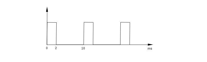
We have a rectangular periodic signal, on/off, with a period of e.g. 20 ms (50 Hz). If the duration of the "on" state is 2 ms, the energy transferred to the receiver will be 10% of the energy that we would transfer if the signal was "on" all the time, so, 20 ms (well, then there would be no rectangular wave signal ...).
If 10ms, then 50%, 18ms - 80% etc.
This can be used to power engines, adjust the brightness of LED lighting, adjust the current in welding machines, or control a little bit "smarter" devices.
Raspberry Pi is able to generate a PWM signal.
The internet is filled with smart tips and programs on this topic. Unfortunately, I could not find anything reliable, so I decided to write about it myself and correct a few circulating myths.
The PWM signal is generated in Raspberry Pi by the BCM2835 chip (different in older models).
It can generate only two PWM signals (PWM0 and PWM1 channels).
They can be modulated differently but both have the same clock frequency.
The PWM0 channel is output to GPIO 12, 18, 40, and 52. PWM1 to GPIO 13, 19, 41, 45, and 53 (GPIO numbering according to Broadcom, alternative wiringPi numbering and physical pin numbers can be displayed using the gpio readall command).
BCM2835 has 54 GPIO pins. Raspberry Pi has a 40-pin connector, so not all of them are led out to the connector. We can use GPIO 12 and 18 (PWM0) and GPIO 13 and 19 (PWM1).
So it is possible to control two devices, and with certain limitations, which will be discussed later, four.
Older Raspberry Pi models, however, have a 26-pin GPIO connector, on which only one PWM signal is led out, GPIO18.
Hence a lot of confusions, it can be found that Raspberry Pi has only one pin with the PWM signal, two (probably a shorthand, because there are two PWM channels), four (in newer models), or 9, because there are actually there, although, not all of them are available.
If we limit our consideration to the newer Raspberry Pi models, with the 40-pin connector, we have:
- Two PWM signals (channels)
- Four pins on the connector block where these signals can appear
- The same signal will appear on the GPIO12 and GPIO18 pins, from channel 0
- The same signal will appear on the GPIO13 and GPIO19 pins, from channel 1
We need, for example, a signal as following: a logical 1 for 2 milliseconds, every 10 milliseconds:
We will use, as in other examples, the wiringPi library. First, programming the PWM generator.
The function:
pwmSetMode (int mode) ;
programs it in the mark:space or balanced mode. As the mode parameter, we will use PWM_MODE_MS or PWM_MODE_BAL, respectively.
The mark: space mode is the traditional approach, signal/no_signal.
I tried to understand the balanced mode, by reading the Broadcom documentation, but I gave up.
Probably I am not the only one. If I find time, I will learn more about this mode and share it here.
For now, we will use the mark:space mode only.
Now, the clock signal. Broadcom writes that the PWM channels are clocked at 100MHz.
In Raspberry Pi, as my measurements show, it is 19.2 MHz. I don't know yet why.
This frequency can be changed by the function:
pwmSetClock (int divisor) ;
The divisor parameter is the value by which the base clock frequency will be divided.
If we use value 192, we get 100kHz clock, if 1920, then 10kHz etc.
10kHz is a pulse every 0.1ms, if we use this divider. This is the accuracy with which we are able to program our generator.
Now we program the period of our signal:
pwmSetRange (unsigned int range) ;
The range parameter is the period of our signal, i.e. the time that elapses between successive pulses.
It is not just time, it is the number of clock ticks per period. If we program the clock at 10 kHz, one tick will last 0.1 ms, so to get the 10 ms period we have to use 100 as range.
Now, we still need to set the GPIO pin, on which we want to have the PWM signal, in the right mode:
void pinMode (int pin, int mode) ;
We use PWM_OUTPUT mode.
Other modes are INPUT and OUTPUT. If we use them, the PWM signal will not appear on the pin.
However, it will remain programmed, we can use it to periodically disabling PWM. I will show an example further in this section.
Now the last function which will allow us to set the duration of a logical 1 and will put the PWM signal to the selected pin:
void pwmWrite (int pin, int value) ;
On the pin pin will appear the PWM signal with the duration of a logical 1 value.
Remember that we can set only four of the Raspberry Pi GPIO connector pins as the PWM signal output.
Similar like in the pwmSetRange function, the value of the value parameter is given as a number of the PWM clock ticks. So, if we want to have a 2 ms pulse and the clock is programmed at 10 kHz, we set the value as 20.
From now on, we have a signal on our GPIO pin. At any moment, we can change its duty cycle by another pwmWrite with a different value.
And how to turn it off? Just set pinMode to OUTPUT or INPUT.
It's time for test programs.
I do not think that each of you has an oscilloscope somewhere around to view and measure the generated signal. I do not have it either. That is why I wrote a simple program markspace.c which measures the duration of a logical 1 and logical 0, and signal period on pin 22 (according to wiringPi).
It's not super precise, the measurement is interfered with by Raspbian's multitasking, but for now, it is good enough.
We compile it with a ready-to-use cms script or manually with the following command:
cc markspace.c -o markspace -lwiringPi
Now we connect pin 22 with the pin on which we want to measure the signal and run the program:
./markspace
If there is any periodic signal on pin 22, the screen will show something like this:
Mark: 4.00 ms Space: 6.00 ms Period: 10.00 ms
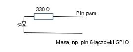
Instead of the markspace program, we can connect an LED diode to the PWM pin, then (at least in some cases) we can see with our own eyes that the PWM works, the brightness of the light will be changing:
First test:
The pwm1.c program and the compilation script cpwm1
We will generate signals with a period of 10 ms and a duty cycle of 10%, 20% ... 90%, each of them will last 3 seconds. The signal can be observed with the markspace program, or you can connect an LED diode between pin 1 (according to wiringPI, which is the 12th physical pin of the GPIO connector) and ground, e.g. the 6th physical pin of the GPIO connector.
After every 3 seconds, the LED diode will glow brighter.
First, we program the PWM0 channel.
Pin 1 (according to wiringPi, physically pin 12) we set to PWM mode:
pinMode (1, PWM_OUTPUT);
We program the mark:space mode of the PWM generator:
pwmSetMode (PWM_MODE_MS);
We set the clock divider to 1920, one tick will last 0.1 ms:
pwmSetClock (1920);
We program the signal period, 100 * 0.1 = 10ms:
pwmSetRange (100);
We run the generator on pin 1, 10% of the duty cycle, which is 1 for 1 ms. To see what is happening, we display information about the duration of a logical 1. We must remember that one tick of our clock is 0.1 ms, so we need 10 ticks to obtain 10 ms:
        printf ("1 ms \ r"); fflush (0);
        pwmWrite (1,10);
        sleep (3);
After 3 seconds, we change the duty cycle to 20%, 2 ms pulse:
        printf ("2 ms \ r"); fflush (0);
        pwmWrite (1.20);
        sleep (3);
And we repeat it every 1 ms up to 9 ms.
It is worth noticing that after our program finishes, the PWM signal will not disappear, but will remain on pin 1, 10 milliseconds with 90% duty cycle, as we programmed it.
Second test:
Now the program that controls three PWM devices. How to do it with only two PWM channels?
It is possible, although the control will not be completely independent.
Two devices must work alternately, never both at the same time, for example, an indicator of a normal operation and an indicator of a malfunction.
You can easily expand this example to four devices, keeping in mind the above-mentioned limitations.
The program, as previously, pwm2.c and the compilation script cpwm2
We program PWM, the signal will be taken from pins 1, 23 and 24 (wiringPi numbering, not BCM).
There will be the same signal on pins 23 and 24, it is one channel, PWM1:
        PinMode (1, PWM_OUTPUT);
        pinMode (23, PWM_OUTPUT);
        pinMode (24, PWM_OUTPUT);
        pwmSetMode (PWM_MODE_MS);
        pwmSetClock (1920);
        pwmSetRange (200);
Now we generate signals on pins 1, 23 and 24, from two different channels:
        printf ("Active pins 1, 23 and 24 \ n"); fflush (0);
        for (i = 0; i <2; i ++)
          {
           pwmWrite (1,5);
           pwmWrite (23.15);
           sleep (1);
           pwmWrite (1.25);
           pwmWrite (23.20);
           sleep (1);
          }
We turn off PWM on pin 24, only devices connected to pins 1 and 23 will be active:
       printf("Aktywne piny 1 i 23\n");fflush(0);
       for(i=0;i<2;i++)
         {
       pinMode(24, OUTPUT);
          pwmWrite(1,5);
          pwmWrite(23,15);
          sleep(1);
          pwmWrite(1,25);
          pwmWrite(23,20);
          sleep(1);
         }
We turn on PWM on pin 24. Unfortunately we have to re-program the generator:
        printf ("Active pins 1, 23 and 24 \ n"); fflush (0);
        pinMode (24, PWM_OUTPUT);
        pwmSetMode (PWM_MODE_MS);
        pwmSetClock (1920);
        pwmSetRange (200);

        for (i = 0; i <2; i ++)
          {
           pwmWrite (1,5);
           pwmWrite (23.15);
           sleep (1);
           pwmWrite (1.25);
           pwmWrite (23.20);
           sleep (1);
          }
Devices connected to alternative pins of the same channel can operate alternately, with different signals, simultaneously, controlled by the same signal, or be selectively turned on or off. It is enough to reprogram the pin's operating mode.