

 Polski
 We have something like this:

We bought it for fun and out of curiosity but also with the intention of using it in a serious project ...
It didn't cost much. So, what can we use it for?
The idea behind is simple. It has only 4 pins. To the VCC pin we connect the power + 5V, and to the GND pin, the ground.
The two remaining pins are for measuring the distance. After putting a TTL 5V pulse on the "Trig" pin, the sensor sends 8 ultrasonic pulses with a 40KHz frequency, receives a reflected from an obstacle echo, and finally, on the "Echo" pin, sends a pulse with the duration proportional to the measured distance.
And here comes my first complaint.
According to the specification, a signal triggering the measurement should last for at least 10 microseconds. In my case, even the shortest signals possible for me to generate were starting the measurement.
And the second, more important issue. On the "Echo" pin, again according to the documentation, appears a signal with a duration from 0.15 ms (2.5 cm) to 25 ms (4.3 m), or 38 ms (6.5 m) in case of the absence of an obstacle reflecting the signal.
If you search the internet, you will find that the working range is actually from 1 to 5 meters.
From where are these differences? Apparently, each manufacturer makes its own version. Some of the differences can be seen straight away, for example, the quartz frequency, type of operational amplifier, or the ultrasonic converter control system.
The microprocessor designation is, as usual, illegible, but evidently, the software differs between devices.
My three tested sensors, which unfortunately came from the same source, behaved identically. After exceeding 90 cm they did not increase the pulse width, even when I was measuring the distance to the clouds.
Ok, but let's start using it.
And here usually comes some simple program for Arduino. We generate a Strob, wait for the Echo signal, measure its duration, divide by 58 and that's it. We ignore noise signals.
However, we will connect our sensor to the Raspberry Pi.
There are two important differences.
The first is the power supply voltage.
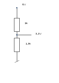
The Raspberry Pi is powered by 5V, but on the GPIO connector pins, the signals are in the CMOS standard, 3.3V. HC-SR04 works in TTL standard, 5V. If you put into the GPIO pin a voltage higher than 3.3V it might cause damage.
And the second important thing is that Raspberry Pi has a multitasking operating system so it is not possible to precisely measure a short period of time. As our process does not have exclusive access to the processor, it may wait its turn until another process or kernel finishes its work.
The first problem is easy to solve by connecting the signal from the Echo pin to the GPIO through an ordinary two resistor voltage divider:
The second problem we will solve by software.
Let's connect the wires:- Sensor's VCC pin to Raspberry Pi's +5V GPIO pin (second or fourth pin)
- Sensor's GND pin to Raspberry Pi's 0V GPIO pin (for example sixth pin)
- Sensor's Trig pin to Raspberry Pi's GPIO 21 pin (twenty-ninth pin)
- Sensor's Echo pin to Raspberry Pi's GPIO 22 pin (thirty-first pin and through a voltage divider)
I chose pins 29 and 31 arbitrarily. You can use other GPIO pins, but these are used in a program that we will discuss in a moment.
The pins' names and numbers can be easily found on the internet, but there is the gpio readall command which might come in handy. It will not only display their names and numbers but also how the pins are programmed:+-----+-----+---------+------+---+---Pi 3---+---+------+---------+-----+-----+ | BCM | wPi | Name | Mode | V | Physical | V | Mode | Name | wPi | BCM | +-----+-----+---------+------+---+----++----+---+------+---------+-----+-----+ | | | 3.3v | | | 1 || 2 | | | 5v | | | | 2 | 8 | SDA.1 | IN | 1 | 3 || 4 | | | 5v | | | | 3 | 9 | SCL.1 | IN | 1 | 5 || 6 | | | 0v | | | | 4 | 7 | GPIO. 7 | IN | 1 | 7 || 8 | 1 | ALT5 | TxD | 15 | 14 | | | | 0v | | | 9 || 10 | 1 | ALT5 | RxD | 16 | 15 | | 17 | 0 | GPIO. 0 | OUT | 0 | 11 || 12 | 0 | OUT | GPIO. 1 | 1 | 18 | | 27 | 2 | GPIO. 2 | OUT | 1 | 13 || 14 | | | 0v | | | | 22 | 3 | GPIO. 3 | OUT | 0 | 15 || 16 | 0 | IN | GPIO. 4 | 4 | 23 | | | | 3.3v | | | 17 || 18 | 0 | IN | GPIO. 5 | 5 | 24 | | 10 | 12 | MOSI | IN | 0 | 19 || 20 | | | 0v | | | | 9 | 13 | MISO | IN | 0 | 21 || 22 | 0 | IN | GPIO. 6 | 6 | 25 | | 11 | 14 | SCLK | IN | 0 | 23 || 24 | 0 | OUT | CE0 | 10 | 8 | | | | 0v | | | 25 || 26 | 0 | OUT | CE1 | 11 | 7 | | 0 | 30 | SDA.0 | IN | 1 | 27 || 28 | 1 | IN | SCL.0 | 31 | 1 | | 5 | 21 | GPIO.21 | IN | 1 | 29 || 30 | | | 0v | | | | 6 | 22 | GPIO.22 | IN | 1 | 31 || 32 | 0 | IN | GPIO.26 | 26 | 12 | | 13 | 23 | GPIO.23 | IN | 0 | 33 || 34 | | | 0v | | | | 19 | 24 | GPIO.24 | IN | 0 | 35 || 36 | 0 | IN | GPIO.27 | 27 | 16 | | 26 | 25 | GPIO.25 | IN | 0 | 37 || 38 | 0 | IN | GPIO.28 | 28 | 20 | | | | 0v | | | 39 || 40 | 0 | IN | GPIO.29 | 29 | 21 | +-----+-----+---------+------+---+----++----+---+------+---------+-----+-----+ | BCM | wPi | Name | Mode | V | Physical | V | Mode | Name | wPi | BCM | +-----+-----+---------+------+---+---Pi 3---+---+------+---------+-----+-----+
To put our sensor to life we need:
- Of course Raspberry Pi with Raspbian (I have not tested other operating systems),
- The wiringPi library (apt-get install wiringPi, if you do not have it, although it's better to install from source and compile according to this manual as sometimes you will have to make minor changes),
- My sample program,
- To save the effort and our fingers, a simple script to compile this program.
If you are not interested in how the program works, that's about it. Compile the ready to use program with the script and run:
./cp
./dist
If by any chance you will see a message:
Permission denied
then almost certainly you need the root user permission.
Log in as root or use the beloved by all Debian enthusiasts magical sudo prefix before the command.
However, if you want to learn more, I invite you to read the rest of the post.
The program is short and simple. It has only 163 lines, but uses interrupts (hardware and software), measures nanosecond delays, and of course, controls the GPIO pins.
Standard Unix header files, but additionally wiringPi.h:
#include <string.h>
#include <stdio.h>
#include <stdlib.h>
#include <unistd.h>
#include <sys/types.h>
#include <sys/resource.h>
#include <time.h>
#include <wait.h>
#include <wiringPi.h>
We define to which pins the sensor's Trig and Echo signals are connected:
#define TRIGPIN 21
#define ECHOPIN 22
Two constants which will be used to fight disruptions:
#define SERIES 100  // how many measurements
#define SERIES1 5  // discard this count of the smallest and largest measurements
According to the sensor manufacturer, to calculate the distance, the duration of the Echo signal must be divided by this value. But the speed of sound in the air depends on temperature. It travels 11% faster at 35 ℃ than at -25 ℃. Perhaps this value should be corrected in special cases:
#define SPEEDDIV 58
The variables' definitions can be found in the attached source code. Let's move to the program.
int main (void)
{
To be able to display diagnostic messages in an easy way, we will use the process PID.
  pid=getpid();
  printf("Start %d\n", pid);fflush(0);
We increase the priority of our process. This will improve the accuracy of the Echo signal's duration measurement. Unfortunately not much, and it will decrease the speed of other processes, however, our distance measuring program is a part of the most important process running on our Raspberry Pi at the moment.
setpriority(0,0,-20);
Now debugging. After sending the USR1 signal to the process, there will be diagnostic messages displayed. The USR2 signal will stop it.
So, kill - USR1 8823 the program talks, kill -USR2 8823 stops talking. This 8823 is the PID of our process which we read and displayed previously.
  signal(SIGUSR1, catch_USR);
  signal(SIGUSR2, catch_USR);
After receiving the USR1 or USR2 signal, the catch_USR function is executed. It sets the debug variable to 1 or 0, respectively:
void catch_USR(int signal_num)
{
fflush(0);
if(signal_num==SIGUSR1)
debug=1;
if(signal_num==SIGUSR2)
debug=0;
}
We initialize the wiringPI library:
  if (wiringPiSetup () == -1)
  exit (1) ;
We program ECHOPIN as input and TRIGPIN as output.
However, ECHOPIN will do more than usual. After changing its signal state, an interrupt will be generated and the int_impuls function will be executed.
    pinMode (ECHOPIN, INPUT) ;
    wiringPiISR (ECHOPIN, INT_EDGE_BOTH, &int_impuls);
    pinMode (TRIGPIN, OUTPUT) ;
To easily calculate the duration of the Echo pulse it is enough to remember in the int_impuls function the time when the signal became one and the time when it fell to zero.
void int_impuls(void) {
      if (digitalRead (ECHOPIN) == 1)
       {
clock_gettime(CLOCK_REALTIME, &tim);
       }
      else
       {
clock_gettime(CLOCK_REALTIME, &tim2);
        impuls=0;
       }
}
One more thing to take care of before we start the measurement. If the process gets an interrupt, sleep (and a few other functions), will not resume.Sleep 10 seconds can take a second, so in this program, we will use our own function:
void Delay(int microsec)
{

 tim3.tv_sec = 0;
 tim3.tv_nsec = microsec * 1000;
     while(nanosleep(&tim3,&tim3)==-1)
          continue;
}
To get rid of disruptions (maybe a bat has flown?), instead of one measurement, we will take 100 of them (#define SERIES 100):
  for(i=0;<SERIA;i++)
   {
Set 0 on the TRIGPIN pin, then, set 1 for 10 milliseconds, and again 0, HC-SR04 will start the measurement:
    digitalWrite (TRIGPIN,0) ; //LOW
    Delay(2);
    digitalWrite (TRIGPIN,1) ; //HIGH
    Delay(10);
    digitalWrite (TRIGPIN,0) ; //LOW
We wait for a pulse on the sensor's Echo pin. When it appears, the int_impuls function changes the value of the impuls variable to 0.
We do not wait forever, because what if there will be no pulse on the Echo pin?
    impuls=1;
    for(k=1;k<9000;k++)
     { if (impuls==0) break;
       Delay(1);
     }
    if (impuls==1)
      {
       printf("Zgubiony impuls\n"); fflush(0);
       tim2.tv_nsec=tim.tv_nsec+1;
      }
We calculate the duration of the Echo pulse, in microseconds, correcting the times saved by the int_impuls function, if any of the measurements happened to be at the end of the second:
    if(tim2.tv_nsec < tim.tv_nsec)
     tim2.tv_nsec= tim2.tv_nsec+1000000000;

    usec[i]=(tim2.tv_nsec -tim.tv_nsec)/1000;
    usectmp=usec[i];
If we send the USR1 signal to the process, the calculated time will be displayed:
if(debug)
printf("%4.1f microsec\n",usectmp);
We wait 90 milliseconds for any eventual ultrasound echo present in the room to disappear. This is in case our program runs in a loop (like the dist.c does).
    Delay(90000);
   }
So now we have 100 measurements. Each one is slightly different. Which is the closest to the true value?
To begin with, we sort the measured values:
qsort (usec, SERIA, sizeof (float), compare_float);
  usectmp=0;
We can display the measured values. They can be weird sometimes.
if (debug)
  for (i=0;i<SERIA;i++)
   { printf(" %d: %3.0f \n", i ,usec[i]); fflush(0);}
We count the sum of the equal measurements, grouping together those that differ only by single microseconds. We reject a certain number of the smallest and the largest measurements:
  for(i=0;i<10000; i++) tab_rob[i]=0;

  for (i=SERIA1;i<SERIA-SERIA1;i++)
   {
     j=usec[i]/10;
// Jesli nie wykryto echa, indeks wyjdzie poza tablice
     if(j<10000) tab_rob[j]++;
   }
We look for the measurement value that occurred the most times. We reject measurements which were less than 50% of the most common. From what is left we calculate the average:
// Znajdz maksimum
  max=0 ;
  for (i=0;<10000;i++)
   if (tab_rob[i]>max)
    max=tab_rob[i];


  for (i=0;i<10000;i++)
   if (tab_rob[i]<max*0.5)
    tab_rob[i]=0;

  sum1=0; sum2=0;
  for (i=0;i<10000;i++)
    if (tab_rob[i] >0)
      {
       sum1=sum1+tab_rob[i];
       sum2=sum2+i*tab_rob[i];
      }
And finally, we have the measurement result. Now we display it, here, together with the time of the measurement. Of course, you can use it further, save it in a database, use it to turn on sirens, or to activate an alarm when approaching an unauthorized distance ...
  usectmp=(float)sum2/sum1;
  time (&czas);
  loctime = localtime (&czas);
  strftime (data, 50, "%Y-%m-%d %H:%M:%S", loctime);
  printf("%s %4.1f cm\n",data, usectmp/SPEEDDIV*10);
 }
The program described here has been used to measure the amount of diesel fuel in a tank of a factory gas station. In a 5000 liter tank, the measurement error is less than 10 liters.