

 Polski
 A cheap RFID reader plus an antenna 2cmx4cm (click on the picture below to see them both):

Unfortunately, I was not satisfied with the antenna sensitivity so I made my own. 50 windings of a coil wire (a black roundel, about 50 mm in diameter, shown on the enlarged photo). The diameter of the winding wire is not very important. Here, I used 0.40 mm.
How does it work?
The RDM630 reader uses the coil to generate an electromagnetic field with a frequency of 125 kHz (there are also other standards but I will not talk about them here).
If we put into the field a so-called transponder, its integrated microcircuit, using the energy of the field, will start working and will send its five-byte identifier.
This identifier is unique. There are no transponders with the same identifier (well, at least shouldn't be. I used to have a box of transponders from some cheap manufacturer, and out of 200 cards, two identifiers were used twice).
The reader will read this identifier and send it to us.
The transponder can be a plastic card, key fob, hermetic module for industrial use, etc.
Here is an example:

So let's get down to work.
We need a reader, a transponder for testing purposes, two resistors, e.g. 1k and 1.9k, and of course Raspberry Pi.
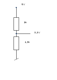
Why do we need these resistors? Well, the Raspberry Pi's GPIO works with 3.3V voltage, and our reader transmits in the 5V standard. The Raspberry Pi is powered by 5V, but the signals on the pins of the GPIO connector are in the CMOS standard, 3.3V. Applying a voltage higher than 3.3V to the GPIO pin may cause damage.
The signal from the reader must be put on the GPIO through an ordinary two resistor voltage divider:
So, we connect the 5V power supply to our reader, the TX output (pin1 of the five-pin connector) through the divider to pin 10 (RX) of the GPIO connector:
- Reader's + 5V pin (5th on the five-pin connector) to Raspberry Pi's + 5V GPIO pin (2nd or 4th physical pin)
- Reader's GND pin (4th on the five-pin connector) to Raspberry Pi's 0V GPIO pin (for example 6th physical pin)
- Reader's RX pin (1st on the five-pin connector) through the divider, to Raspberry Pi's RX GPIO pin (10th physical pin)
The documentation for RDM630 can be easily found on the Internet, but for convenience, I also copied it here.
And here we encounter the first problem. We need exclusive access to the Raspberry Pi's UART serial port. However, it can be already used as a console port or by Bluetooth. If after issuing the following command:
gpio readall
we see that TX and RX pins are in ALT5 mode, as shown in the table below, we have to do some preparatory work.+-----+-----+---------+------+---+---Pi 3---+---+------+---------+-----+-----+ | BCM | wPi | Name | Mode | V | Physical | V | Mode | Name | wPi | BCM | +-----+-----+---------+------+---+----++----+---+------+---------+-----+-----+ | | | 3.3v | | | 1 || 2 | | | 5v | | | | 2 | 8 | SDA.1 | IN | 1 | 3 || 4 | | | 5v | | | | 3 | 9 | SCL.1 | IN | 1 | 5 || 6 | | | 0v | | | | 4 | 7 | GPIO. 7 | IN | 1 | 7 || 8 | 1 | ALT5 | TxD | 15 | 14 | | | | 0v | | | 9 || 10 | 1 | ALT5 | RxD | 16 | 15 | | 17 | 0 | GPIO. 0 | OUT | 0 | 11 || 12 | 0 | OUT | GPIO. 1 | 1 | 18 | | 27 | 2 | GPIO. 2 | OUT | 1 | 13 || 14 | | | 0v | | | | 22 | 3 | GPIO. 3 | OUT | 0 | 15 || 16 | 0 | IN | GPIO. 4 | 4 | 23 | | | | 3.3v | | | 17 || 18 | 0 | IN | GPIO. 5 | 5 | 24 | | 10 | 12 | MOSI | IN | 0 | 19 || 20 | | | 0v | | | | 9 | 13 | MISO | IN | 0 | 21 || 22 | 0 | IN | GPIO. 6 | 6 | 25 | | 11 | 14 | SCLK | IN | 0 | 23 || 24 | 0 | OUT | CE0 | 10 | 8 | | | | 0v | | | 25 || 26 | 0 | OUT | CE1 | 11 | 7 | | 0 | 30 | SDA.0 | IN | 1 | 27 || 28 | 1 | IN | SCL.0 | 31 | 1 | | 5 | 21 | GPIO.21 | IN | 1 | 29 || 30 | | | 0v | | | | 6 | 22 | GPIO.22 | IN | 1 | 31 || 32 | 0 | IN | GPIO.26 | 26 | 12 | | 13 | 23 | GPIO.23 | IN | 0 | 33 || 34 | | | 0v | | | | 19 | 24 | GPIO.24 | IN | 0 | 35 || 36 | 0 | IN | GPIO.27 | 27 | 16 | | 26 | 25 | GPIO.25 | IN | 0 | 37 || 38 | 0 | IN | GPIO.28 | 28 | 20 | | | | 0v | | | 39 || 40 | 0 | IN | GPIO.29 | 29 | 21 | +-----+-----+---------+------+---+----++----+---+------+---------+-----+-----+ | BCM | wPi | Name | Mode | V | Physical | V | Mode | Name | wPi | BCM | +-----+-----+---------+------+---+---Pi 3---+---+------+---------+-----+-----+
Edit the /boot/cmdline.txt configuration file (remove console startup) and /boot/config.txt configuration file (remove Bluetooth startup and enable UART if disabled).
It is difficult to give unambiguous instruction on how to do it as it looks different depending on the Raspbian versions. I recommend looking it up on the internet.
In my Raspbian (10.4), in the /boot/cmdline.txt file I had to remove console = tty1, and in the /boot/config.txt file, add:
enable_uart=1
dtoverlay=pi3-disable-bt-overlay
dtoverlay=disable-bt
dtoverlay=miniuart
In Raspbian 9.8 the patches looked like this:
enable_uart = 1
dtoverlay = miniuart
dtoverlay = pi3-disable-bt
dtoverlay = disable-bt
and delete or comment out:
#dtparam=audio=on
Then, I had to stop the following processes:
systemctl disable hciuart.service
systemctl disable bluealsa.service
systemctl disable bluetooth.service
After rebooting the system, the serial port should be available.
Now, let's talk about the program.
As always, you can find a ready-to-use example program available here.
To compile and run it use the following commands:
cc rdm.c -o rdm
./rdm
After the first compilation you will most probably have to change the permissions to the file:
chmod 754 rdm
But how does it work?
First, we program the serial port. I already explained how to do it in the SMS sending program section.
The problem may occur when opening the serial port:
if((pd = open("/dev/ttyAMA0",O_RDWR | O_NDELAY |O_NONBLOCK)) != -1)
The BCM2835 chip in Raspberry Pi (different in older models) has two serial ports. If you are interested in technical details, I recommend reading the documentation
Without going into details, if it doesn't work on ttyAMA0, in the line of code above replace ttyAMA0 with ttyS0.
After each card reading, the reader sends to the serial port:
- byte 02 as a marker of start of transmission
- 10 bytes of card ID
- CRC byte (XOR from card ID bytes, those 5 stored on a card)
- byte 03 as a marker of end of transmission
The ID bytes are sent as ASCII codes. For example, byte 7A is sent as two characters, 37H and 41H (hexadecimal), hence 10 characters instead of 5.
The interesting part of the card reading program starts here:
In an infinitive loop we read data from the serial port:
 for(;;)
  {
The two lines of code below require some explanation. When the transponder enters the antenna's electromagnetic field, the reader sends several readings.
I don't know why, but sometimes 3, sometimes 7, the following readings are sent only if we remove and again approximate the transponder.
Therefore, after each reading, we wait a couple of seconds, and then, we read all the bytes from the UART buffer. This way, we get rid of multiple card readings.
// remove multiple card readings
    sleep(1);
     while(  read(pd, &znak, 99) > 0) ;
Now we wait for byte 02H, start of transmission:
     znak[0]=0x00;
     while (znak[0] != 0x02) // start of card ID
      {
       read(pd, &znak[0], 1);
      }
    n=0;
We read the next 11 bytes which are ASCII codes of the card's ID and CRC. We ignore the end of transmission byte 03H, it will be removed by the mechanism shown below:
    for(;;)
     {
       if ((a=read (pd, &znak, 1)) != -1)
        {
         karta[n] = znak[0];
         n++;
         if (n>11) break;
        }
     }
We do not check the CRC. Experience shows that reading errors are very rare, and anyway, our program will look up the card ID in a database to determine, for example, owner's permissions.
We replace CRC byte with 00H byte, the end of string mark in C language:
//  remove CRC
       karta[10]=0x00;
And now we have to do something with this obtained ID, for example, check it in a database, save it to a file ...
In our example program we simply display it:
       printf("karta: %s\n", karta); fflush(0);
  }