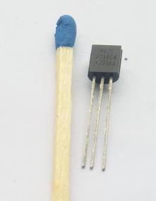
It cost me nearly nothing:
DS18B20 temperature sensor with 1-wire interface.
Just to be clear, it is this "bead with three wires" on the right side 🙂 .
Connect the power supply and we are ready to measure the temperature.
Measurement range from -55 to 125 ° C, accuracy ± 0.5 ° C in the range -10 to 85 ° C.

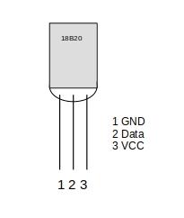
As we can see, this sensor has three pins: ground, power supply (3 - 5.5V), and a 1-Wire bus signal.
We do not need the power line. This sensor can draw the required power from the data line but with some limitations. We will talk about it later.
We will not discuss here how the 1-wire bus works. It is covered pretty well on the internet so I will mention just a few basic things.
- The devices communicate with each other using serial communication over the signal wire.
- To the common signal wire is connected one controller (there may be more, but then they must cooperate with each other to prevent transmission on the bus at the same time) and many receivers.
- Each receiver has a unique number (64 bits, including 8 bits for a checksum, which gives 256 addresses).
- Using a special protocol, the controller detects a device on the bus and manages the transmission, making sure that only one device is active at a time.
- All the devices on the bus, the controller as well, have open collector outputs. The bus must be connected to power line with a resistor (typically 4.7kΩ, although with a long bus and bigger number of receivers it might be necessary to reduce this value).
- Each receiver has an 800 pF capacitor that stores energy that can be used for powering the device. This allows only two wires to be connected to the receiver which is then powered from the signal wire. In some cases, however, there might be problems with the communication, the energy in the capacitor may be insufficient, the receiver will reset. Reducing the pullup resistance value to e.g. 1 kΩ may help a bit.
- The transmission speed is low, 16.3 kbit/s, the recommended bus length is up to 30 meters, although, under certain conditions (low-capacity cables, special transmitters, etc.) it can be increased up to 500 m.
Well, no more boring things, let's plug it in.
- Pin 1 of the sensor to Raspberry Pi ground, e.g. to pin 9.
- Pin 2 of the sensor to pin 1-wire Raspberry Pi, default GPIO4 (pin 7).
- Pin 3 of the sensor to the power supply, e.g. 3.3V, Raspberry Pi pin 1.
- Close pins 2 and 3 of the sensor with a 4.7 kΩ resistor (pullup).
(GPIO numbering according to BCM)
Anticipating the questions, it is not enough to use the GPIO pin's internal pullup resistors. They have a resistance of 40 kΩ, too much for the 1-wire bus. If we really do not want this extra resistor, we can use GPIO2 or GPIO3 pins. They are designed for I2C communication and have built-in 1.8kΩ pullup resistors. Of course, then we will not be able to use i2C. I haven't tested it, but it should work.
Now, we start the 1-wire in Raspberry Pi. By default, this bus is not active, so either enable it using the raspi-config command, or, in the /boot/config.txt file, add the following line:
dtoverlay=w1-gpio
This will start the 1-wire controller on the default pin, GPIO4.
If for some reason we want to use a different pin, we can define it, for example, for GPIO17:
dtoverlay=w1-gpio,gpiopin=17
Unfortunately, it will be necessary to reload the system, but the good news is, that this is all we have to do to start measuring the temperature.
After restarting the system, the 1-wire bus modules should be loaded:
   root@minircp:~# lsmod |grep w1
   w1_therm               28672  0
   w1_gpio                16384  0
   wire                   36864  2 w1_gpio,w1_therm
The devices will appear in the /sys/bus/w1 location:
   root@minircp:~# ls /sys/bus/w1/devices/
   28-23b10b000900  w1_bus_master1
The w1_bus_master1 is our 1-wire bus controller, the 28-23b10b000900 is our temperature sensor.
Of course, there will be more devices corresponding to the 1-wire bus devices if we connect them. The controller will distinguish them from each other based on their unique 64-bit number.
But how to read this temperature? An example program would be handy, some library ...
Well, it is easier this time. All you need to do is to read the contents of the /sys/bus/w1/devices/28-23b10b000900/temperature file:
   root@minircp:~# cat /sys/bus/w1/devices/28-23b10b000900/temperature
   25000
   root@minircp:~#
25000 is the temperature measured by the sensor, in °C, multiplied by 1000, which in our case is 25.00 °C.
We can easily read it using any language, and then do what we intend to do with it.
Display it, turn on a fan, turn off a heater, send an SMS about overheating of the server room, save in a database of daily temperatures on Kilimanjaro ...


 Polski