

 Polski
 My new toys:


The LCD display with the HITACHI HD44780 chip.
Very popular, available in many versions differing in backlight color, number of text rows and columns.
In addition, it does not cost much, depending on the version and store, of course.
Descriptions of how to connect it and display something on it can be found on the internet, so I will not repeat them here.
We will use the wiringPi LCD devLib library and focus on how to connect more than one display to the Raspberry Pi.
Can it be done? Of course it can, over a dozen to one Raspberry Pi.
Let's start!

The display has 16 pins:
- Ground.
- Power supply +5V, through two rectifiers in forward direction.
- Contrast. We apply this voltage between 0 and 5V, from a potentiometer or two resistor voltage divider.
- RS. If we apply LOW to this pin, then the state of the D0-D7 line will be recognized as a command, if HIGH - as data.
- RW. Write/Read. Since we will only write to our display, we connect this pin permanently to ground.
- E. A falling edge of the signal on this pin triggers reading and interpreting the status of the D0-D7 data bus.
- D0. Data bus bit 0.
- D1. Data bus bit 1.
- D2. Data bus bit 2.
- D3. Data bus bit 3.
- D4. Data bus bit 4.
- D5. Data bus bit 5.
- D6. Data bus bit 6.
- D7. Data bus bit 7.
- A. +5V as display backlight power supply.
- K. Display backlight power supply ground.
Why power supply by two diodes?
On the GPIO connector, a logical 1 is 3.3V. For the display, a logical 1 is 0.7xVDD (supply voltage), so for 5V, it will be 3.5V. If we connect the GPIO pin with the display pin, it will either not work or the signal will be susceptible to interference.
The voltage drop across the two diodes will cause the VDD of the display to drop to about 3.5V, so the voltage of a logical 1 will be 2.45V.
The display can work in 8-bit or 4-bit mode. That is how it was constructed.
In 8-bit mode, all lines of the data bus are used, in 4-bit mode, lines D4 - D7.
We will use the second option here, the 4-bit mode - let's not waste the GPIO outputs!
And now, the cables:| Display's pin | Connect to |
|---|---|
| VSS | Ground, e.g. GPIO pin 6 (physical). |
| VDD | Power voltage +5V, e.g. GPIO pin 2 (physical). |
| V0 | We connect the slider of the potentiometer connected in between VSS and VDD. Resistance - just use whatever you have at hand, I used a 4.7kΩ trim potentiometer. |
| RS | We connect to pin GPIO.23. We will talk about alternative pins later. |
| RW | Since we will only write to the display, we connect this pin to ground. |
| E | We connect to pin GPIO.25. |
| D0-D3 | We do not connect, we do not need these pins, we will use the 4-bit mode. |
| D4-D7 | We connect respectively to pins GPIO.29, GPIO.28, GPIO.27, GPIO.26. |
| A | We connect with +5V power supply. |
| K | We connect with ground. |
I chose those GPIO pins arbitrarily. You can use any other GPIO pins, however, these were used in example programs that we will cover in a moment. If for some reason, you want or need to use others, remember to modify the source code.
These are convenient because they group together nicely on the GPIO connector. With one 10-pin plug, we can connect everything except power.
A simple program for checking if the cables are correctly connected:
#include <string.h>
#include <stdio.h>
#include <stdlib.h>
#include <wiringPi.h>
We need the wiringPi.h header!
/*  zmienne  */
static int lcdHandle ;
A simple function that displays text in column x and row y of the display's screen:
void wyswietl(int x, int y, char* tresc)
{
  lcdPosition (lcdHandle, x, y) ; lcdPuts (lcdHandle, tresc) ;
}

/* S T A R T */
main (argc, argv)
     int argc;
     char *argv[];
{
The initialization of the WiringPi library structures:
if (wiringPiSetup() == -1)
  {
        printf("wiringPi-Error\n");
    exit(1);
  }
Now, the initialization of our display:
int lcdInit (int rows, int cols, int bits, int rs, int strb, int d0, int d1, int d2, int d3, int d4, int d5, int d6, int d7) ;
Here, we define what type of display we use, in what mode it works, and where we connected the signals.
The number of rows, the number of columns, mode (4/8 bits), RS, and E.
The next 8 values are the numbers of the GPIO pins to which we connected the display data bus.
And here a few words of explanation:
If we use the 8-bit mode, everything looks simple and logical. The next parameters' items of the lcdinit function are D0, D1, etc. of the display.
In 4-bit mode, however, for some reason, the manufacturer used pins D4-D7, not D0-D3. See the display's pin assignment table.
So, in the lcdInit function, we have D0=29, D1=28, D2=27, and D3=26, but these bits are physically connected to the display's D4, D5, D6, and D7.
lcdHandle = lcdInit (4, 16, 4, 25,23,29,28,27,26,0,0,0,0) ;
We clean the display's screen:
lcdClear (lcdHandle) ;In the following rows, we display the next arguments with which we called our program. For simplicity, all from column 0:
  wyswietl(0, 0, argv[1]);
  wyswietl(0, 1, argv[2]);
  wyswietl(0, 2, argv[3]);
  wyswietl(0, 3, argv[4]);
}
Copy out the discussed program or download its source code.
Compile the program:
cc wyswlcd1.c -o wyswlcd1 -L/usr/local/lib -lwiringPi -lwiringPiDev
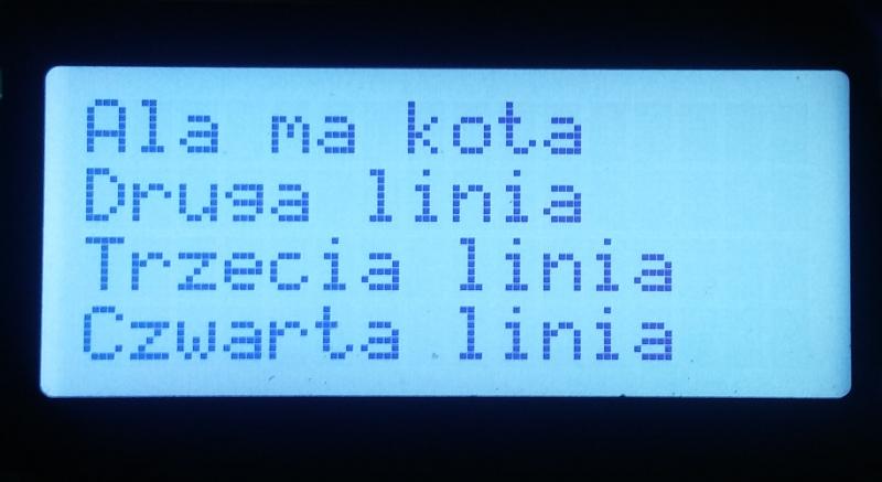
Run the program (in this example, the displayed text is in Polish):
./wyswlcd1 "Ala ma kota" "Druga linia" "Trzecia linia" "Czwarta linia"
If all went well, on the display's screen you will see:
But we were supposed to connect to Raspberry Pi more displays!
We need 4 pins for data and 2 for RS and E.
We have 17 GPIO pins at our disposal, in a condition as they were prepared by Raspbian. It seems that we can connect only two displays because 3 * 6 is already 18.
Not too bad, data lines and RS can be common to all displays.
They use them only when the falling edge of the signal appears on E (strobe)!
So we only need 5 common GPIO pins and one separate for each display.
17 - 5 = 12, this is how many displays we can handle.
And maybe even more because Raspberry Pi has 28 GPIO pins. If we reprogram them, and who says we can't, we can connect even 23 displays.
So let's do it, connect the second display.
All pins parallel to the first one, except for E (strobe), which we connect to GPIO.24.
Now we upgrade our program.
A few changes to the program, highlighted in bold.
For each display, we execute icdInit indicating the GPIO pin to which its E pin (strobe) is connected.
In the following code, the fifth lcdInit parameter, pins 23 and 24.
We program the next displays in the same way.
static int lcdHandle ;
static int lcdHandle1 ;


void wyswietl(int x, int y, char* tresc)
{
  lcdPosition (lcdHandle, x, y) ; lcdPuts (lcdHandle, tresc) ;
}
void wyswietl1(int x, int y, char* tresc)
{
  lcdPosition (lcdHandle1, x, y) ; lcdPuts (lcdHandle1, tresc) ;
}


lcdHandle = lcdInit (4, 16, 4, 25,24,29,28,27,26,0,0,0,0) ;
lcdHandle1 = lcdInit (4, 16, 4, 25,23,29,28,27,26,0,0,0,0) ;

if (atoi(argv[1]) == 0)
 {
  lcdClear (lcdHandle) ;
  wyswietl(0, 0, argv[2]);
  wyswietl(0, 1, argv[3]);
  wyswietl(0, 2, argv[4]);
  wyswietl(0, 3, argv[5]);
 }
else
 {
  lcdClear (lcdHandle1) ;
  wyswietl1(0, 0, argv[2]);
  wyswietl1(0, 1, argv[3]);
  wyswietl1(0, 2, argv[4]);
  wyswietl1(0, 3, argv[5]);
 }
We modify our program or download its ready-to-use version.
Compile it:
cc wyswlcdn.c -o wyswlcdn -L/usr/local/lib -lwiringPi -lwiringPiDev
Run it (in this example, the displayed text is in Polish):
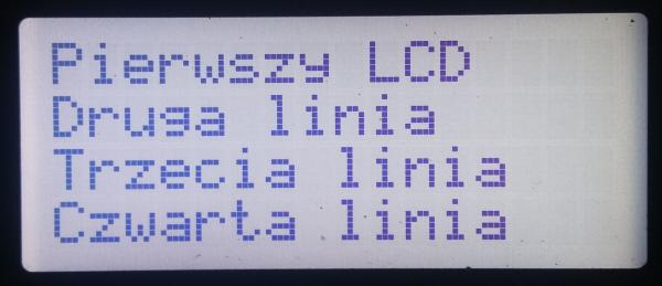
./wyswlcdn 0 "Pierwszy LCD" "Druga linia" "Trzecia linia" "Czwarta linia"
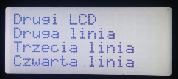
./wyswlcdn 1 "Drugi LCD" "Druga linia" "Trzecia linia" "Czwarta linia"
If all went well, something like this will appear on the screen of the first display:
The second one will display:
To easier understand the principle of operation of the described program, I tried to simplify it as much as possible. I have left only the necessary fragments.
Of course, nothing comes for free. Each time the program is launched to display the content, the lcdInit function is executed for all displays, causing them to reset. Adding a new display requires modifying the source code.
If we use the mechanisms described here, in a more complex program, these inconveniences will disappear.
We use this type of displays to show instructions during the breathalyzer test in our sobriety checkpoint system and refueling process in our factory gas station system.